and historical purposes, all rights reserved.
This page is copyright© by
This page may not be sold or distributed without
the expressed permission of the producer
I have no connection with any camera Co.
This camera manual library is for reference
and historical purposes, all rights
reserved.
This page is copyright© by
![]() ,
M. Butkus, NJ.
,
M. Butkus, NJ.
This page may not be sold or distributed without
the expressed
permission of the producer
I have no connection with any camera Co.
On-line camera manual library
If you find this manual useful,
how about a donation of $3 to:
M.
Butkus, 29 Lake Ave.,
High Bridge, NJ 08829-1701
and send your e-mail address
so I can thank you.
Most other places would charge
you $7.50 for a electronic copy
or $18.00 for a hard to read Xerox copy.
This will help
me to continue to host this site,
buy new manuals, and pay their shipping costs.
It'll make you feel better, won't it ?
If you use Pay Pal, use the link below.
Use the above address for a check,
M.O. or cash.
Back to main camera manual page
Problems opening PDF
files or printing problems
- click here
Click
here for Bronica SQ-A HTML
manual converted to PDF
Click here for scanned PDF
direct from manual- color
|
Specifications of the ZENZA BRONICA SQ-Am Parts of the ZENZA BRONICA |
|
|
SQ-Am |
|
|
1. Loading the Batteries 2. Battery checking 3. Exchanging Lenses 4. Functions on the Hand Grip |
|
|
5. Shutter Release Warning LED 6. Attachment and Removal of Film Back 7. Construction of Film Back |
|
|
8. Film Loading 9. ASA/ISO Film Speed Dial 10. Film Type Indicator Frame 11. Auto-Winding and Shutter Winding .. 12. Exposure Counter 13. Film Unloading 14. Setting the Shutter Speed Dial 15. Time(T) Exposure 16. Setting the Aperture |
|
Type |
6 x 6cm format auto-winding lens shutter single lens
reflex camera, with interchangeable lens, |
|
Frame size |
film back, finder and focusing screen systems. 55.6 x 55.6mm |
|
Film |
120 roll film (12 exposures); |
|
Standard lens |
220 roll film (24 exposures); 135 roll film in film cartridges; and Polaroid® Land Pack films. (Exclusive film backs for each film type.) Zenzanon-S 80mm F2.8; interchangeable type lens; six elements in four groups; multi-layer |
|
Filter size |
anti-reflection coated; 51° angle of view; F22 minimum
aperture; and minimum 0.8m focusing distance. 67mm diameter on 50mm to 250mm lenses; and 95mm diameter on 40mm and 500mm lenses. |
|
Lens mount |
Exclusive four-claw Bronica SQ bayonet mount. |
|
Focusing adjustments |
Helical focusing system built into each lens. |
|
Lens diaphragm |
Fully automatic instant reopening lens diaphragm action;
equal-distant aperture scale graduations. |
|
Shutter |
Electronic control SEIKO #0 between-lens leaf shutter; shutter speeds 8 sec. to 1/500 sec., |
|
Film winding |
without intermediate settings, plus T (time exposure);
mechanical control 1/500 second. Motorized automatic film winding action. |
|
Multiple exposure |
Multiple exposure possible with multiple exposure lever
on camera main body. |
|
Mirror lock-up |
Mirror lock-up possible with the mirror lock-up switch
lever on the camera main body, with two settings - |
|
Mode selection |
S - Mirror returns automatically after
shutter release action. C - Mirror stays locked up for continuous mode operation. Mode changes with mode selector switch on the handgrip, with three settings - |
|
OFF - All power is switched OFF and the shutter is locked.
Sm - Single mode operation (single frame exposed). Cm - Continuous mode operation (consecutive frames exposed). |
| Film back | Exclusive film backs
for 120, 220 and 135 roll films and Polaroid& Pack film. Daylight loading interchangeable type; with 'ASA/ISO film speed dial coupling to finder with built-in exposure meters. |
| Finder | Interchangeable finder system |
| Focusing screen | Interchangeable type. Standard type, supplied with camera, has split-image rangefinder spot surrounded by microprism ring and full-area matte screen. Flash synchronization X-setting (for all speeds up to 1/500 second). |
| Battery checking | Red-colored LED indicator
lights up at the rear end of the shutter speed scale window when the
battery check button is depressed (for checking the electronic shutter 6-volt power source). |
| Batteries | Single 6-volt silver
oxide or alkaline-manganese battery for the electronic shutter system;
Six AA-size alkaline-manganese or NiCd batteries for the motor drive system. |
| Firing speed | Continuous shooting
or single frame exposures at the rate of 3 frames per 2 seconds (ap
proximately) is possible with the fastest shutter speed. |
| Shutter speeds usable | All shutter speeds can be used with auto-winding (also possible with finders having built-in exposure meters). |
| Number of frames | Approximately 500 frames can be exposed when fresh alkaline-manganese batteries are used (at normal ambient temperature) |
| Others | Drive button, Over-load warning LED, Shutter release warning LED, Remote Control terminal, External power terminal, Hot-Shoe |
| Dimensions | 144.5(wide) x 93(high)
x 132mm(long) - SQ-Am main body only. 144.5(wide) x 109(high) x 179mm(long) - SQ-Am main body, with standard lens, Film Back SQ 120 and Waist-level Finder S. |
| Weight | 960 grams (SQ-Am
main body, without batteries) 1,925 grams (SQ-Am main body, with standard lens, Film Back SQ 120 and Waist-level Finder S but without batteries.) |
The above specifications are subject to change with or without prior notice.
 |
 |
 |
 |
 |
 |
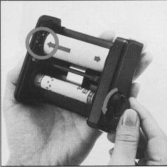
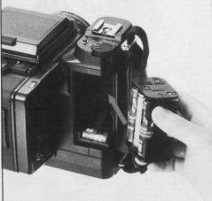
1. Loading the Batteries
A single 6 volt silver oxide battery
or alkaline-manganese battery is required for the electronic
control lens shutter. The electronically-controlled
shutter system will not work without
loading the battery. The shutter will be mechanically
controlled when the battery is not
loaded and will be released at 1/500 sec., regardless
of the setting on the shutter speed
dial.
Six 1.5 volt AA-size
alkaline manganese or NiCad batteries are required for
the motor drive system.
However, the performance
noted in the specifications will
not be possible when manganese batteries
are used because of their electrical characteristics.
*The batteries noted may be
obtained at any photographic equipment or electrical appliance
shop.
|
|
|
 |
 |
 |
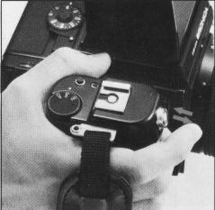
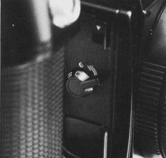
A. Set the mode selector switch
to Sm or Cm and then depress the battery check button. If a red-colored LED
lights up at the rear end of the shutter speed scale window, the battery for
the electronic shutter is loaded properly and there is sufficient power for
operations. * If the LED does not light up, (1) Mode selector switch is on "OFF"
position, (2) the battery is not loaded properly or (3) it is completely drained
and should be exchanged.
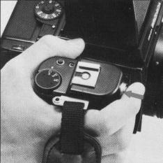
B. The batteries
for the motor drive system are checked by setting the mode selector switch to
Sm or Cm and depressing the drive button to check whether there is motor drive
operation or not.
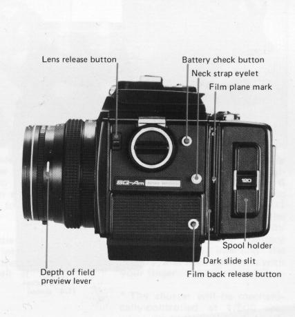
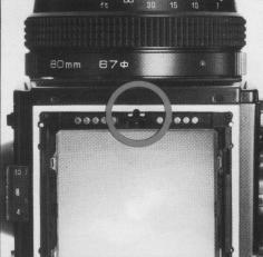
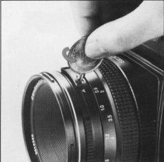
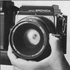
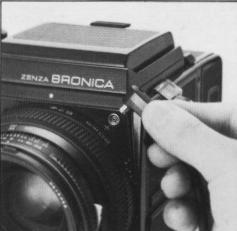
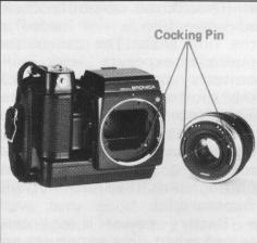
3. Exchanging Lenses
The Zenza Bronica SQ-Am will not operate properly
unless the lens is attached. Furthermore, it will not be possible to attach
or remove the lens unless both main body and lens are in the "wound" condition,
with the winding pin on the lens positioned between the red-colored band and
green-colored dot and the winding pin of the body set to the green dot. When
the winding pins are not located properly for attaching the lens, simply move
the winding pin of the lens to the green dot manually, with your finger, and
press the drive button to wind the lens shutter when the winding pin of the
main body is not located at the green-colored dot.
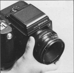 |
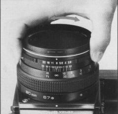
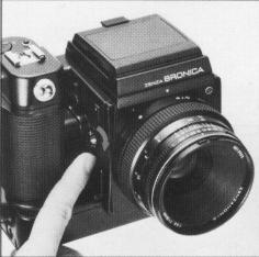
A. To attach the lens to the body, align the orange dot on the camera main body and the red dot on the lens, and then insert the lens fully into its mount. Rotate in the counterclockwise direction until it stops, with an audible click, which will indicate that it is securely locked. |
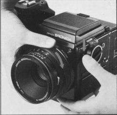 |
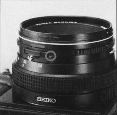
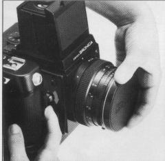
B. To detach the lens, press the lens release button down and, at the same time, rotate the lens in the clockwise direction until it makes a full stop, at which point it will be possible to detach the lens. |
4. Functions on the Hand-Grip
 |
A. The mode selector switch has three settings, or OFF, Sm and Cm. When set to OFF, all power is switched OFF and auto winding, lens shutter operation and the built-in exposure meter of attached finders will not function. When set to Sm, there is single exposure operation and when set to Cm, there is continuous exposures while the shutter release button is depressed. |
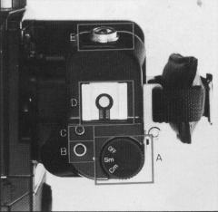 |
B. The drive
button is used to set the loaded film to the first frame to be exposed,
after it is aligned to the start-mark, to advance the film for multiple
exposures, etc. C. When there is abnormal overload on the motor during film winding operations, etc., the motor will stop and the red colored overload warning LED will light up. Therefore, move the mode selector switch to OFF, check for the cause of the overload and rectify it. Then, set the mode selector switch to Sm or Cm and it will be possible to continue shooting. OFF, check for the cause of the overload and rectify it. Then, set the mode selector switch to Sm or Cm and it will be possible to continue shooting. |
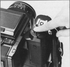
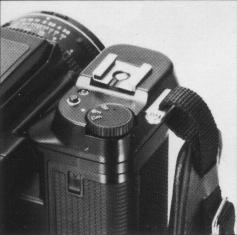
D. The accessory shoe
is a hot shoe type which means that electronic flash units with proper terminals
can be used without connecting cords. However, the contact cover on the hot
shoe must be removed, first, when attaching electronic flash units.
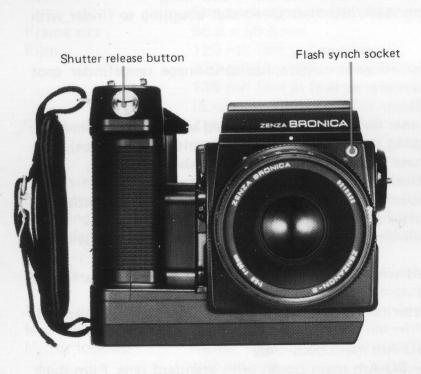
E. Depress the shutter release button gently,
with the ball of the finger.
When the
shutter release button is stroked gently and smoothly, it will be possible to
confirm the shutter speed setting in the viewfinder area of the AE Prism Finder
S, when it is attached.
5. Shutter Release Warning
LED
 |
In the following
cases, the shutter will not be released and a shutter release warning
LED will light up, outside the screen area, in the top center of the
finder: 1 . Dark slide is inserted. 2. Lens is not attached properly. (Same with automatic extension tubes, too.) 3. Lens release button is depressed. 4. Film is not advanced. (Same when exposure counter is between "S" and "1 ".) 5. Batteries for motor drive operation does not have sufficient power. |
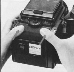
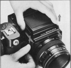
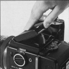
6. Attachment and Removal
of Film Back
The film back is a film chamber that can be attached or detached
freely, thus permitting free exchange of film types even during shooting sessions.
The film back is fully coupled to the
camera main body, upon attachment. Therefore, the shutter will not be released,
even when the shutter release button is depressed if the film back is attached
with the film still not advanced properly, and the shutter release warning LED
will light up instead. The drive button should be used, in this case, to advance
the film one frame.
On the other hand,
should the drive button be depressed when a film back is attached with film
advanced properly and, therefore, in condition for photography, the film will
not be advanced.
Thus, it is possible
to choose the film type most suited to the shot, even midway in the roll. An
ASA/ISO film speed dial is available on the film backs and can be used for setting
the film speed of the film loaded in the film back, as there is automatic
coupling when finders with built-in exposure
meters are attached on the camera body. This will, of course, be very convenient
when using films of different sensitivities in the film backs.
* Make full use of the interchangeable film back.
1. Color and black-and-white, in different film speeds, can be shot, as required.
2. Continuous shooting is possible if sufficient preloaded film backs are available.
3. Don't waste unsuitable film used in a previous session but simply load up
a new film back with the required film type.
4. A Single SQ-Am can
be used by many in the studio or at home, by using additional film backs.
* Film backs are available optionally.
Therefore, the type meeting the requirements of the photographer should be chosen.
|
|
|
|
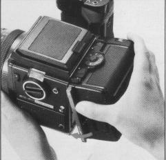
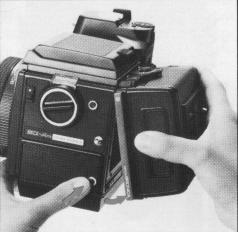
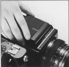
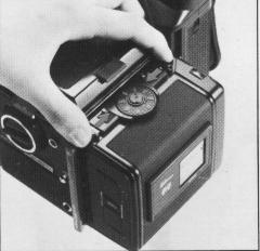
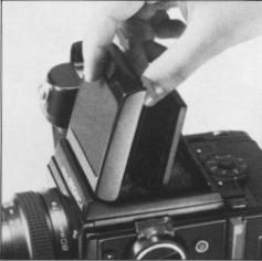
A. To attach the film back to the camera main body,
simply insert the latches at the upper end of the film back into the attachment
openings at the upper end of the camera main body. Then, press the lower end
of the film back against the body until it locks securely.
*The dark slide must be withdrawn from its slit, upon
attachment of the film back to the main body, as otherwise the shutter cannot
be released. Furthermore, there is danger of the film back accidentally becoming
detached from the main body, should the dark slide be left in its slit while
the camera is being carried. Therefore, make it rule to withdraw the dark slide
promptly upon attaching the film back to the main body.
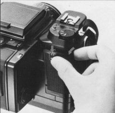
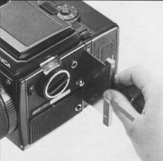
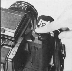
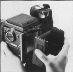
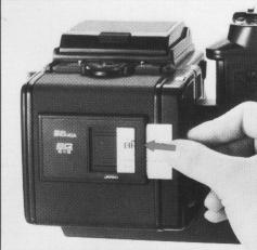
B. To remove the film back from the camera main body, insert
the dark slide into the dark slide slit, as illustrated, with the O mark on
the dark slide at the top end. Push it all the way in.
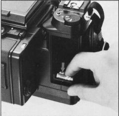
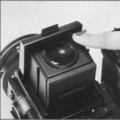
C. Depress the film back
release button and the lower end of the film back can be removed, as illustrated.
Simply shift the film back up slightly and pull it away.
* The dark slide cannot be withdrawn from the film
back when the film back is detached from the camera main body.
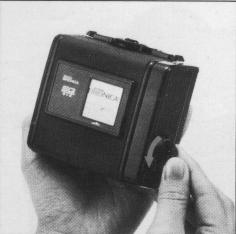
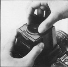
7. Construction of Film Back
|
|
|
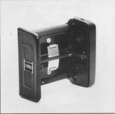
A. The film back consists of a film holder and a film back
frame, with exclusive film backs available for 120 and 220 roll films.
The film holder has an insert or frame for loading
film, as well as a built-in film winding mechanism. B. The film back frame has
a base with a dark slide slit and a back cover with an ASA/ISO film speed dial
and a film type indicator frame. The film back frame completely encloses the
film holder and shields it from outside light, as well as connecting it to the
camera main body and also coupling with the finders with built-in exposure meter.
8. Film Loading
 |
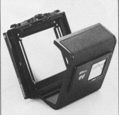
A. To open the back cover, squeeze the left and right back cover release buttons, in the arrow-indicated directions, at the same time and the back cover will open. |
 |
 |
 |
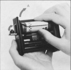
| B. The film holder can be taken out for film loading, upon opening the back cover. | C. There are two
spool holders on the film holder. The top one is for the fresh film
spool while the bottom one is for the empty take-up spool. The left-side
shaft of spool holder can be opened by pushing the fresh film spool
outward in the arrow indicated A direction. Therefore, insert the right
end of the spool on to the right-side shaft, which is fixed, and then
close the left-side holder (shaft) which will engage the spool. * The spool holders on the left side will be locked securely, when the back cover is closed. |
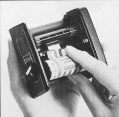
D. After
loading the fresh film spool properly, draw out the leading end of the
film and turn it across the film pressure plate (as illustrated). Run
it down and turn it over to the take-up spool. Insert the leading end
into the slit of the take-up spool and wind slightly until securely
engaged. * The inside black surface of the leader must face out when running across the pressure plate, in this case. |
|
|
|
|
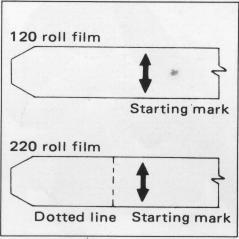
| E. Lift up the hinged flap and rotate the manual film winder on the right side of the film holder in the arrow-indicated direction. When the starting point, or arrow mark, on the leader is aligned with the triangular start-mark on the top left side of the film holder, stop rotation. | F. Close the back cover, by pressing it firmly against the base of the film back, as illustrated. The back cover will automatically close and lock. The same operation will close the back cover when the film back is detached from the main body. | G. Upon loading the
film, set the mode selector switch to Sm or Cm and depress the drive
button, which will place the first frame into position for taking the
picture. The exposure counter will also change from "S" to "1" and the shutter will also be wound. |
|
|
|
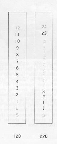
| H. When the film back is detached from the camera main body for film loading, the manual film winder is used for advancing the film. The film will stop when it is in place for the first exposure, with the exposure counter also changing to "1 ". However, it will be possible to rotate the manual film winder and, therefore, it should be rotated 2 or 3 times more, in order to take up any slack in the loaded film. | * When loading 220
roll film in the Film Back SO 220, do not mistake the dotted line before
the arrow mark for the start-mark. * See the instructions supplied with Film Back SO 135 for proper use of the 135 roll film. |
9. ASA/ISO Film Speed Dial
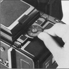 |
To set the film sensitivity
of the film loaded in the film back, revolve the ASA/ISO film speed
dial with a slight lifting action, as illustrated, and set the film
speed scale to the index. There are click-stops at 1/3rd increments,
in this case. (The dial can be revolved in either direction) * The ASA/ISO film speed dial is automatically coupled to the finder with built-in exposure meter, when attached. |
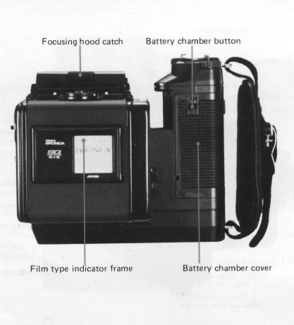
10. ISO Film Type Indicator Frame
 |
Upon loading the film, tear off the end flap from the empty film package and insert it in the film type indicator frame. This will help you keep track of the film loaded in the film back, even when two or more film backs are used with different films. At the same time, set the film speed with the ASA/ISO film speed dial, as it will come in handy when using the finder with built-in exposure meter. |
11. Auto-Winding and Shutter Winding
|
|
|
| A. When the mode selector switch is set to Sm, the film will be advanced one frame and the shutter will be wound, after which motor operation will be suspended, each time the shutter release button is depressed and the picture taken. To take the next picture, therefore, the finger should be lifted from the shutter release button and then used to stroke the shutter release button once more. | B. When the mode
selector switch is set to Cm, there will be continuous photography (with
continuous auto-winding and shutter winding action), as long as the
shutter release button is depressed. * The mirror lock-up switch lever should be set to N, except when shooting with the mirror locked up. (See page 29 on Mirror Lock-Up.) |
12. Exposure Counter
 |
The exposure
counter shows the number of frames exposed or, in other words, is an
additive type. Starting from "S", the counter on Film Back SQ 120 shows
numbers from 1 to 12, while Film Back SQ 220 shows numbers from 1 to
24. The letters "S", "12" and "24" are orange-colored while all other numbers are white. |
 |
13. Film Unloading
 |
A. After the 12th
exposure of the 120 roll film (24th exposure of the 220 roll film),
the film only will be advanced until the remaining film and leader paper
is wound up on the take-up spool. Open the back cover when the motor suspends operations. B. Remove the film holder and,
while preventing the loose film from unwinding, take out the take-up
spool. Seal the exposed film and return it to its original box until
development. |
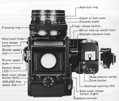
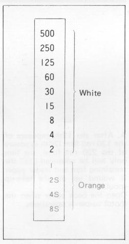
14. Setting the Shutter Speed Dial
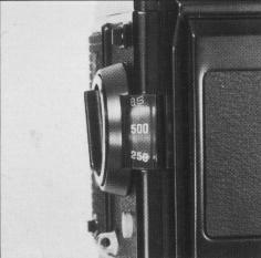 |
A. The shutter speed
scale is viewed in its window over the shutter speed dial. The numbers
on the scale are shutter speed settings, with numbers 1 to 8S full numbers
and numbers 2 to 500 fractions of a second. For examples, "8S" is 8
sec., "2S" is 2 sec. and "500" is 1/500 sec., but no intermediate setting
between click stops are possible. |
 |
* The shutter is released at 1/500 sec., regardless of the
setting when the battery is not loaded or is completely drained.
B. The numbers on the scale are color-coded in orange and white.
Orange-colored numbers are full number settings of 1 second and longer while
white colored numbers are setting from 1/2 to 1/500 second. There is no B (bulb)
setting. See the page 21 for time (T) exposures.
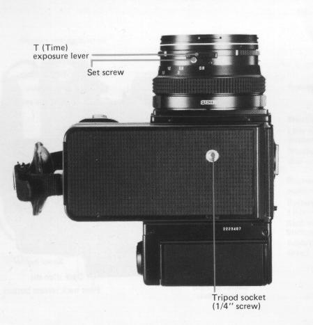
15. Time (T) Exposure
 |
Time exposures are
made with the time exposure lever on the lens, regardless of the setting
on the shutter speed scale. However, the lever is locked to prevent
accidental movement and, therefore, must be unlocked for use. Except when using the lever for time exposures, always shift it so that the letter "A" is visible on the lens barrel and tightly lock its set screw to prevent accidental movement. |
 |
A. Unscrew the set
screw on the time exposure lever until further revolution is not possible,
which will permit the lever to be moved freely. B. Slide the time exposure lever and expose a red-colored "T" on the lens barrel. Depressing the shutter release button, in this condition, will open the shutter. The shutter is closed by shifting the time exposure lever and exposing the letter "A" once more. However, since the film will not be advanced to the next frame, in this case depress the drive button to advance the film. |
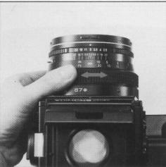
16. Setting the Aperture
 |
 |
A. The aperture ring
is rotated, in either direction, to set the required f/number opposite
the white index dot. The aperture ring click-stops at the numbered settings.
Intermediate settings are also possible. * Intermediate settings cannot be used when the finders with built-in exposure meter are used. |
B. All interchangeable lenses for the Zenza Bronica SQ-Am
have fully automatic lens diaphragms which means that the focusing screen is
always viewed at the full aperture, with the brightest possible image. However,
depressing the depth of field preview lever will stop the lens diaphragm down
to the preselected lens opening and permit the photographer to check the depth
of field effect on the focusing screen.
* The aperture ring must not be adjusted while the
depth of field preview lever is being depressed.
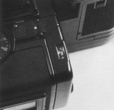
17. Interchanging Finders
|
|
|
| A. The finder can be interchanged, with other optional finders, to match shooting conditions to photographic conditions. To attach the finder, align the front end of the finder with the front end of the finder frame on top of the camera main body, as shown. Then, gently lower the finder and, when well-seated, slide forward until it locks. | B. To detach, simply
depress the finder release button, while, at the same time, sliding
the finder backwards where it can be taken up. |
18. Waist-Level
Finder and Interchanging Magnifiers
 |
A. The focusing hood
of the waist-level finder is opened by pushing up on the focusing hood
catch at the rear end of the folded waist-level finder. * There is no standard finder for the Bronica SQ-Am, with the user having a choice of several finders. Instructions are based on the waist-level finder because of its popularity. |
 |
 |
 |
|
B. The magnifier is flipped into viewing position, by
simply sliding the release lever in the arrow-indicated direction. To
store the magnifier, simply push it down until it catches. * The magnifier can be exchanged for one matching the eyesight of the user. |
C. To close the focusing hood, first, push down the magnifier (if it is in viewing position). Next, press in both side frames, as illustrated, and, at the same time, press the front frame back towards the rear. The focusing hood will automatically be folded down. | D. The standard magnifier
supplied with the waist-level finder has a power of -1 .5 diopters,
which can be exchanged for others with powers of -4.5, -3.5, -2.5, -0.5,
+0.5 and +1 .5 diopters. These optional accessories should be purchased
to suit the user's eyesight, if necessary. Simply rotate the magnifier frame in the counter-clockwise direction to unscrew. Attach in the reverse manner |
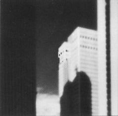
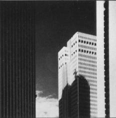
19. Focusing Adjustments
|
|
|
|
| A. The lens is focused on the subject, by rotating the focusing ring in either direction, while checking the effect on the microprism / split-image rangefinder spot in the center of the focusing screen (standard type). | B. The central split-image spot splits the image into two, with the upper and lower halves separated horizontally when the lens is out of focus. When in focus, however, the two halves will coincide with the displacement disappearing. The microprism ring surrounding the central spot can also be used for checking the sharpness of the focused image, since the image will glitter when the lens is not focused. The surrounding full-area matte surface can also be used for checking image sharpness. | |
20. Distance Scale and Depth of Field Scale
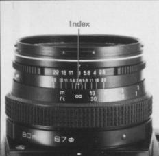 |
A. Distance scales on the Zenzanon-S lenses can be used for focusing at the required distance or finding the distance actually focused. Simply rotate the focusing ring and set the required distance opposite the orange-colored index, which will adjust the lens for the required distance. |
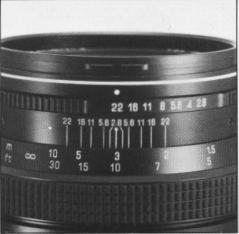 |
B. There is an apparent
zone of sharpness, both in front and back of the focused subject, which
is known as the depth of field. The depth of field scale shows the zone
of apparent sharpness at any lens opening or distance and can be utilized
for quickly and simply ascertaining the depth of field. The depth of
field scale is next to the distance scales and is made up of identical
pairs of apertures on both sides of the orange-colored distance index.
These identical pairs of apertures indicate the distance that will be
in focus at these lens openings. For example, if
the 80mm lens is focused at a distance of 3m, it can
be seen from the depth of field scale that the zone will extend from
2 to 7 meters (6 ft. to 23 ft.), when a lens opening of F22 is used. * See the depth of field table for the Zenzanon-S 80mm lens, on page 40. |
21. Infrared Photography
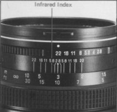 |
In infrared photography,
some adjustment must be made in the focus in order to retain sharpness
on the film, because the invisible infrared rays are longer in wave
length than the visible rays used for focusing. For
infrared photography 1. Use a R filter or equivalent with an infrared (black-and white) film. |
2. The red-colored line, next to the orange-colored distance
index, is the infrared index.
3. After
focusing in the normal manner, re-set the distance indicated by the orange colored
distance index to the infrared index, by shifting the distance ring.
4. Follow instructions enclosed with the
infrared film and filter and, to be on the safe side, make several bracketing
shots. In general, more exposure rather than less seems to be a safe guide.
22. Flash Photography
 |
A. Always use flash
cords with a standard PC type plug. When detaching the flash cord, grip
the plug firmly and pull it out straight, instead of using a twisting
action.
B. The lens shutter of the Zenzanon-S lens has a X-setting
for flash synchronization, which means that electronic flash units will
synchronize at all shutter speed settings, up to the fastest 1/500 second.
|
23. Multiple Exposures
|
|
|
| A. To make multiple exposures, turn the multiple exposure lever in the arrow-indicated direction before exposing the first shot. When the shutter release button is depressed, in this condition, the shutter will be released any number of times without advancing the film. | B. Upon completing the multiple-exposure picture, be sure to return the multiple exposure lever back to its vertical position and depress the drive button to advance the film one frame. If the drive button is not depressed, the next frame will also be a multiple-exposed one. |
24. Mirror Lock-Up
 |
 |
 |
| A. The mirror lock-up
switch lever has three settings - N (normal) - For shooting with
out mirror lock-up. S (single frame) - For shooting single frame with mirror lock-up. C (continuous) - For shooting continuously with mirror lock-up. * Always use the AE Prism Finder S in the manual mode, when shooting with the mirror locked up. |
B. For shooting with the mirror locked up, rotate the mirror lock-up lever in the arrow indicated direction and coincide S or C to the index. The lens shutter will close completely and the reflex mirror and film safety plate will swing up. | C. The shutter will be released when the shutter release button or electro-magnet release is depressed. |
 |
 |
D. When S is set
to the index, with the mirror lock-up switch lever, the lever will automatically
return to N, with the next film advancing and shutter winding action.
And, following shots will, of course, be normal.
E. When C is set to the index, with the mirror lock-up switch lever, however, the lever will not return to N with the next film advancing and shutter winding action but will stay locked up any number of times. |
D. When shooting is suspended,
after mirror lock-up, and the mirror lock-up switch lever is rotated from S
or C to N, shutter release and motor operation will take place but the film
will not be advanced with the result that the next exposure will be double-exposed.
Double exposure can be prevented, in the above case, by the following methods.
* After
completing the 12th exposure or 24th exposure, the film only will be advanced
automatically and the motor will suspend its operation. Should new film be loaded
and the drive button depressed, with the mirror lock-up switch lever at C, the
film will be placed into position for exposing the first frame with the mirror
locked up. The mirror lock-up switch lever must always be returned to N, before
loading film.
 |
 |
| a) Cover the lens
and then use the mirror lock-up switch lever to return to N. Then, continue photography in the normal manner. |
b) Utilize film back interchangeability and detach the film back before rotating the mirror lockup switch lever to N. Attach the film back after motor operations take place and is suspended. |
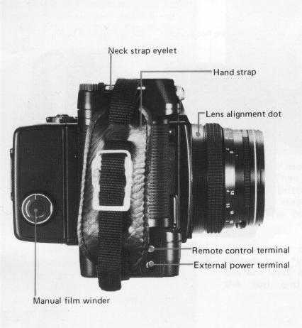
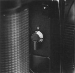
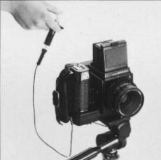
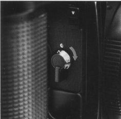
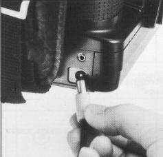
25. Remote Control Operations
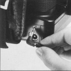 |
Remote control shutter
release operations will be possible by inserting a 2.5mm mini-plug into
the remote control terminal on the Zenza Bronica SQ-Am. Equipment which
can be used, in this case, are remote control extension cord, wireless
remote control equipment, interval meter, etc., which are available
in most photographic equipment stores. However, always check operation
of the equipment before actual use. Resistance of the extension cord
should not exceed 30 ohm, too. *The mini-plug of the' remote control equipment must be attached or removed with the mode selector switch at OFF, as otherwise the shutter will be released if the mode selector switch is at Sm or Cm. |
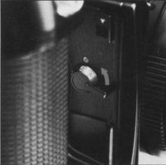
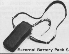
26. Use of External Power
 |
Inserting the plug of an external power source into the external power terminal automatically switches power supply to the motor drive system from the internal battery power (six AA size batteries) to the external power. The battery holder must be left inside the battery chamber even when taking power from an external source. The NiCd batteries cannot be recharged inside the battery chamber but must be recharged externally and then used. |
 |
Optional accessories, such as
external power source plug, NiCd battery recharger, AC adapter,
etc, are not supplied but equipment meeting the following
specifications and conditions will
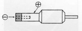
be acceptable. 1. External power plug: Plugs used for transistor radios and tape recorders are acceptable. 2. External power conditions: Voltage - DC 9 Volt; Current - 5 Ampere. |
 |
3. Cable conditions: The cable from the external power
to the SQ-Am should be as short and thick as possible, or - Less than 2 meter length with cable of 0.3 sq mm area, or Less than 5 meter length with cable of 0.75 sq. mm area. * Do not mistake the polarity (+ and -) marks, when using the plug.* An optional External Battery Pack S (six UM-2 or C-type batteries) is also available as an external power source for continuous shooting sessions. |
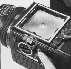
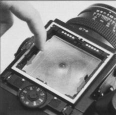
27. Interchanging Focusing
Screens
 |
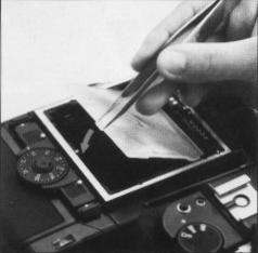 |
A. The focusing screen
can be exchanged, depending on the type of photographic work being undertaken.
First, remove the finder attached to the camera main body. Then, move the screen removal levers on both sides in the arrow-indicated directions, as illustrated. Then, using a pincer or similar tool, lift up the screen with the protrusion at the rear end. |
Different screens.
B. To install the focusing screen, nest the protrusion at
the rear end of the screen in a corresponding groove on the camera main body.
Then, slide both screen removal levers forward to secure the focusing screen.
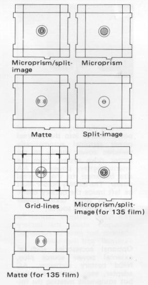
* Seven types of focusing screens are available.
28. Attachment of the Neck Strap
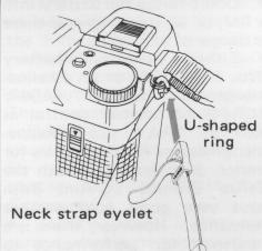 |
A. First, insert the U-shaped ring into the neck strap eyelet, as illustrated. |
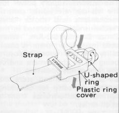 |
B. Next, place the plastic ring cover over the U-shaped ring, as illustrated. |
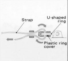 |
C. Next, thread the neck strap through the plastic ring cover (and the U-shaped ring) and pull it out, as illustrated. |
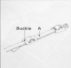 |
D. After adjusting the length of the neck strap, pass the leading end of the strap through the buckle, as illustrated, which will fix it securely. |
29. Facts about the Battery
"There
should be no slack in the strap between the buckle and the plastic ring cover,
or in "A" section, which means that both straps must be of the same length at
this point.
The batteries supply power
for the various electronic control mechanisms and motor drive mechanisms incorporated
in the Zenza Bronica SQ-Am. When used incorrectly, there is possibility of the
wrong exposure being set to the camera and/or the camera not operating. Be sure
to use and store the battery correctly for obtaining optimum performance from
it at all times.
• Take the battery out
of the battery chamber, and set mode selector switch to "OFF" position when
storing the camera.
• Leaving the battery
in the camera for a long time, without using it, can lead to leakage problems
and result in poor contact.
Discard a
battery with leakage or corrosion and thoroughly clean out the battery chamber,
before inserting a new battery.
• Clean
the contacts of the battery chamber and battery with a soft cloth. Don't use
sandpaper or emery cloth.
• For motor
drive system, use fresh batteries with same brand name. When replacing the batteries,
replace all six batteries at the same time.
• Don't throw the battery into a fire, or hit it strongly, as
there is danger of explosion.
• Either
a silver oxide battery (No. 544/PX28) or an alkaline manganese battery (A544/
4LR44) for shutter control as well as "AA" size alkaline manganese or NiCad batteries
for motor drive are used with the Zenza Bronica SQ-Am. Both have very good cold
weather resistance. However, there is a tendency for performance to drop when
the temperature falls below 0°C (32°F). Therefore, make it a rule to use a new
battery and/or keep replacement batteries on hand for shooting outdoors in freezing
weather. Keep the battery (and camera) under cover, next to the body, and load
just before beginning the session and/or, preferably, use the optional Remote
Camera Battery Pack E and External Battery Pack S.
30. Pointers on Shooting
• The shutter cannot be wound when film is
not loaded in the film back. The use of the multiple exposure lever will, however,
permit you to wind the shutter, in such instances. This feature is, of course,
very convenient for familiarizing yourself with the camera and for testing the
shutter in flash photography. (See "23 Multiple Exposures".)
• Battery power is not consumed when time exposures are made.
• The voltage will drop when the camera
is used for long shooting sessions in freezing weather. Insert new batteries
or keep a spare on hand, for such occasions. Furthermore, keep such batteries
in an inside pocket.
• The focusing screen
is detachable, for exchanging with other types. Do not place trimming masks
or tapes on the bottom surface of the screen, as this will lead to inaccurate
focusing.
• If the mode selector switch
is set to OFF when the AE Prism Finder S is attached to camera main body, battery
power will not be consumed even the power source switch of the AE Prism Finder
S is set to ON.
• In case the voltage
of 6 volt battery for the shutter operation drops and the battery checker LED
does not light up, the shutter will be mechanically controlled at 1/500 sec.
and there will be no automatic film winding by the motor. In such case, if the
battery is removed, then the shutter will be released at 1/500 sec. and the
film will be advanced automatically by the motor.
• It should be remembered, when taking pictures, that the final
print will not be a square format, especially in the economy size, but will
be cut down on both sides or at the top and bottom.
31. Care of the ZENZA BRONICA SQ-Am
• Restrict cleaning of the reflex mirror
to blowing or brushing with the blower brush or a soft camel hair brush. Don't
touch the surface with your fingers or a cloth.
• Use lens cleaning tissue and liquid to clean the surface of
the lens. Do not use silicon coated cloth for this purpose, as it will prove
detrimental to the lens coating.
• Clean
the plastic focusing screen in the same manner. Don't touch the surface as you
may leave fingerprints.
• Protect your
camera from temperature changes which can result in moisture condensation, frost,
etc., inside the body, leading to rusting of metallic parts and troubles.
• Protect your camera from impact and
vibrations, too.
• Upon attaching the
film back, always pull out the dark slide from its slit.
• Always protect the lens with its cover, when carrying the camera.
• Clean the camera and lens very carefully
after using it outdoors in wet weather or at the seashore.
• Wipe the camera carefully with a well-wrung damp cloth, using
fresh water, if the exterior is effected by salty air. Then, wipe it dry with
a soft, dry cloth. If necessary, send it out for a quick inspection at an authorized
repair station.
• If the equipment is
not being used for a long period, store everything in tin-lined containers,
with plenty of desiccant, such as silica gel. Finally, store the equipment in
a cool, dry and well-ventilated (but not windy) place.
• Do not thread too strongly, when using a longer-than standard
tripod screw, as you may damage the body.
 |
• Both camera main
body and lens must be in the "wound" condition to attach or remove the
lens. In other words, when "wound" the winding pin of the lens will
be set between the red band and green dot, while the winding pin of
the body mount will be set to the green colored dot. When not set in the above manner, the winding pin of the detached lens (also Automatic Extension Tube) can be set by moving it manually to the green colored dot, while the winding pin of the SQ-Am main body is set by depressing the drive button. |
• Always clean all exposed contact points before attachment,
as otherwise there will be faulty contact which will lead to improper operations.
• See that exposed contact points are not short-circuited
with a metal object.
*When using the flash synch socket on the camera body,
always cover the hot shoe with its protective cover.
On the other hand, when using the hot shoe, cover the
flash socket with its cover. Otherwise, an electric shock may be received from
the uncovered contact.
• Never insert/remove
the mini plug of the remote control equipment with the mode selector switch
set at Sm or Cm.
• Do not use the external terminal with external power
exceeding 10 volts.
*When a finder with a built-in exposure meter is attached
for photography and a film of different sensitivity is loaded in the film back,
always remember to readjust the ASA/ISO film speed dial for the new film.
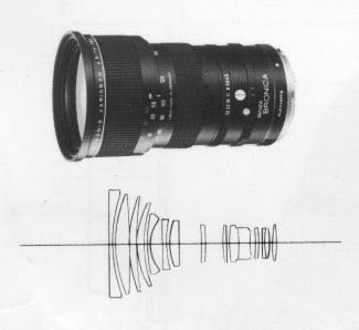
33. Specifications of Zensanon-S Lenses
|
|
|
|
|
|
|
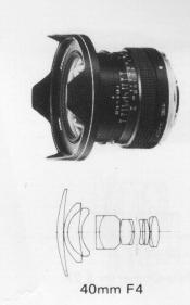
40mm F4 |
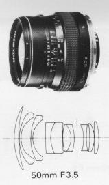
50mm F3.5 |
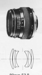
80mm F2.8 |
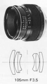
105mm F3.5 |
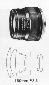
150mm F3.5 |
|
|
No. of group-element
|
8 - I I |
8 - 10 |
4- 6 |
4- 6 |
5- 5 |
|
Angle of View |
87° |
76° |
51° |
41° |
30° |
|
Apertures |
4 -22 |
3.5-22 |
2.8-22 |
3.5-22 |
3.5-22 |
|
Minimum focusing distance (M) |
0.4 |
0.5 |
0.8 |
0.85 |
1.5 |
|
(1.3ft) |
(1.6ft) |
(2.6ft) |
(2.8ft) |
(4.9ft) |
|
|
Filter size (mm) |
95 |
67 |
67 |
67 |
67 |
|
Overall length (mm) |
83 |
62 |
52 |
60 |
61 |
|
Weight (grams) |
660 |
560 |
470 |
540 |
590 |
|
Equivalent focal length in 35mm format camera (mm) |
21 |
28 |
45 |
58 |
85 |
|
|
|
|
|
|
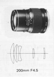
200mm F4.5 |
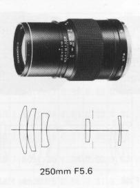
250mm F5.6 |
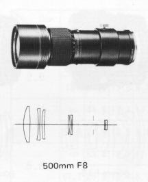
500mm F8 |
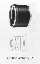
Tele-Converter S 2X |
||
|
No. of group-element |
5 - 5 |
5- 5 |
6 - 7 |
5 - 6 |
|
| Angle of View |
22°30" |
18° |
9° |
||
|
Apertures |
4.5-32 |
5.6-32 |
8 -45 |
||
|
Minimum focusing distance (M) |
2.5 |
3 |
8.5 |
||
|
(8.2ft) |
(9.8ft) |
(28ft) |
|||
|
Filter size (mm) |
67 |
67 |
95 |
||
|
Overall length (mm) |
97 |
129 |
255 |
53 |
|
|
Weight (grams) |
740 |
870 |
1 ,890 |
500 |
|
|
Equivalent focal length in 35mm format camera (mm) |
105 |
135 |
280 |
||
 |
 |
| Zenzanon-S Variogon
75-150mm F4.5 Zoom Lens Lens construction: 13 groups in 15 elements
Angles of view: 53°30' - 30°6' Apertures: 4.5 -32 Diaphragm: Fully automatic Minimum focus: 1.8m (0.25m in macro mode) Filter size: Series 9a (diameter 93mm) Size: 100mm x 152mm Weight: 1,800 grams (3.96 lbs) Accessory: Filter retainer, lens hood, lens case, front lens cat) & rear lens caps |
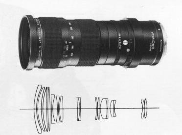
Zenzanon-S Variogon
140-280mm F5.6 Zoom Lens Lens construction: 14 groups in 17 elements
Angles of view: 30°42' -16'12' Apertures: 5.6 '- 32 Diaphragm: Fully automatic Minimum focus: 2.5m (0.76m in macro mode) Filter size: Series 9a (diameter 93mm) Size: 94mmo x 221 mm Weight: 2,000 grams (4.4 lbs) Accessory: Filter retainer, lens hood, lens case, front lens cap & rear lens cap. |
.
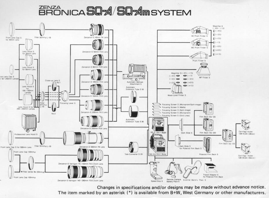
Click here for image of Zenza Bronica SQ-A System